Measurement setup
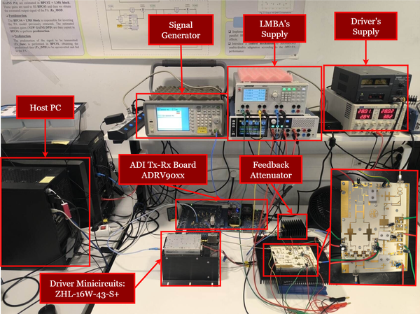
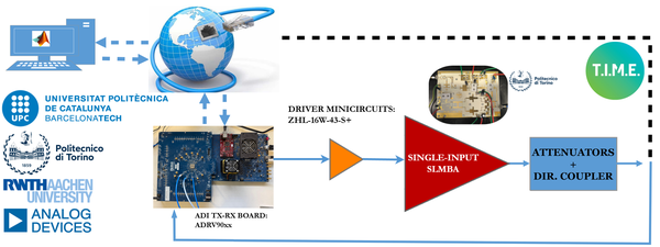
The remoteUPCLab infrastructure enables users to remotely transmit and receive beyond-5G waveforms for DPD benchmarking. It is based on Software-Defined Radio (SDR) transceivers provided by ADI, which performs both signal generation and acquisition. These transceivers interface with a control PC running a MATLAB SFTP server application, allowing users to upload baseband I/Q signals and retrieve the corresponding measured output signals.

In the intermediate phase of the project, the focus is on the linearization of a Load Modulated Balanced Amplifier (LMBA). Operating with a center frequency of 3.7 GHz, the LMBA features a single-input architecture based on GaN-based Power Amplifier (PA) provided by Dr. Vittorio Camarchia and Dr. Anna Piacibello from PoliTO. The peak output power level from the LMBA is limited to approximately 45 dBm.
The PA will be driven by a 200 MHz instantaneous bandwidth signal centered at 3.7 GHz. This signal consists of five aggregated carriers, each occupying 40 MHz. Throughout the competition, the test signal will vary, with carriers being selectively activated or deactivated across iterations. The Digital Predistortion (DPD) algorithm must demonstrate robustness under these changing conditions.
The goal emphasizes not only improving linearity performance but also enhancing the power efficiency of the LMBA. Power consumption will be monitored, and power efficiency, along with output power, Error Vector Magnitude (EVM), and Adjacent Channel Power Ratio (ACPR), will factor into the overall score, as outlined in the System and Scoring details section. Additionally, the number of coefficients used in the DPD function will influence scoring.

The remoteUPCLab server receives baseband I/Q waveforms from remote users. These signals are downloaded onto the ADI board, which upconverts them to generate the RF signal. The same ADI board handles RF down-conversion and data acquisition of the output waveform from the PA. The resulting I/Q data is then sent back to the remote user for DPD processing.
The PA will be operating with varying input signals with a maximum of 200 MHz instantaneous bandwidth. The baseband clock that will be employed in the signal processing operations is 983.04 MHz, which also corresponds to the IQ A/D and D/A sampling frequencies.
Share: